Introduction
The Workflow module guides the user step-by-step into transforming a volume using a rigging, skinning and posing technique.
Typically, the anatomical pose of a voxelized model is limited by the imaging device used to acquire the underlying data, e.g., MRI and CT scanners have narrow entries. Changing the pose of an already acquired voxelized anatomical model enables new processing of human anatomy in a wide variety of poses. The workflow module allows an operator to specify a rigging that represents the anatomical pose of an existing voxel model, manipulate that rigging into a different anatomical pose, and then generate a new voxelized model that represents the original model resampled into that new position.
This module applies the Skeletal animation technique initially conceived for surfaces to voxelized models.
Details
Author: Julien Finet, Kitware
Contributor #1: Johan Andruejol, Kitware
Acknowledgements: This work is supported by the Air Force Research Laboratories.
Contact: Julien Finet
Use Cases
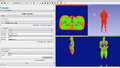
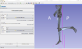
2mm labelmap volume loaded in workflow
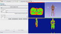
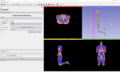
Bone and skin surfaces extracted from 2mm labelmap volume
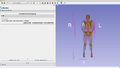
Pose surface with bone model
Parameters
Advanced properties
The Advanced properties can be shown or hidden by clicking on the  expanding button.
- Advanced Workflow: Show/Hide advanced controls at each step of the workflow.
- Advanced properties are automatically set by the workflow logic for a "standard" processing. Nonetheless it is possible for the user to tweak those parameters.
- Note that all the parameters are not exposed even in "Advanced Workflow" mode. The full list of parameters is available in the specific module panels that can be opened by clicking the "Go to XYZ" buttons.
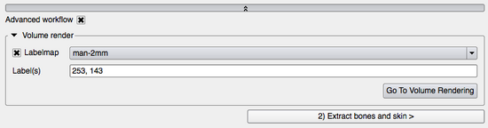
Volume render
At anytime, the Volume render helps to visualize, inspect a volume/labelmap.
- Labelmap: Select the volume/labelmap you want to volume render. The checkbox next to labelmap controls whether the rendering is visible or not.
- Label(s): List all the label(s) that should be visible (i.e. opacity > 0.), all the other labels will be hidden (i.e. opacity = 0.). Labels must be separated with a ',' (comma).
- Go To Volume Rendering: Opens the Volume Rendering module. It gives full control over the volume rendering parameters such as the color and opacity transfer functions, shading, rendering quality...
|
 Advanced properties panel |
1) Adjust labelmap
The Adjust labelmap is the first step of the workflow. The user select here the volume to pose and can optionally prepare the volume before computation is applied.
A) Labelmap
This section makes sure the input labelmap has the right color table associated with it and is in the right coordinate system.
Simple workflow
- Volume: Select the volume/labelmap that you want to reposition. Read here the instructions to load data into Bender. The choosen volume will be automatically set as the default volume for all the following steps.
- Colors: Select the color transfer function to apply to the volume. It is assigned to the volume when Apply is clicked. For each voxel intensity, a unique color is associated and is used at display time. It is important to select the right transfer function of the volume because the color names in the color transfer function are used in the [[#B.29_Merge_labels|Merge labels] section. Grayscale means the volume is not a labelmap and there is no color transfer function associated to it.
- Apply: Set the color transfer function to the volume.
- LPS<->RAS: Apply a (-1,-1, 1) transform to the volume. It can be used to apply the same coordinate system used by Bender to the volume. The "R,L,A,P,S,I" letters on the purple box in the 3D view represent the orientations "Right, Left, Anterior, Posterior, Superior, Inferior".
Advanced workflow
- Go To Volumes: Go to the Volumes module to read volume information (such as its size, origin, spacing, scalar type, range...) and display properties (window/level, threshold, interpolation...)
B) Merge labels
This section provides the functionality of merging the bones labels and the skin labels of the input labelmap to ease the visualization/usability of the bones and the skin that often have different labels in the input 'raw' labelmap.
Some labelmaps can have different labels for representing bones (e.g. bone marrow, bone cancellous, skull...). The Bender workflow handles only 1 label for the bones and 1 label for the skin. It is important to merge those similar labels into a unique label (1 for the bones, 1 for the skin).
Simple workflow
- Output Labelmap: Select the output labelmap that will contain all the labels of the input labelmap and the merged labels.
- Merge labels: Merge the Bone Label(s) and Skin Label(s) from Input Labelmap (into respectively Bone Label and Skin Label) and outputs the result in Output Labelmap. This process simplifies the extraction and visualization of the Bone Model and the Skin Model (see 2) Extract Bone and Skin).
Advanced workflow
- Input Labelmap: Select the input labelmap that needs labels to be merged together. By default, it is Volume in A) Labelmap.
- Bone label(s): Choose the label(s) that will be merged into Bone Label. They are automatically selected from the input volume color table (set in A) Labelmap) by looking for color names containing the strings "bone" or "vertebrae".
- Bone label: Select the new label value of Bone Label(s).
- Skin label(s): Choose the label(s) that will be merged into Skin Label. They are automatically selected from the input volume color table (set in A) Labelmap) by looking for color names containing the string "skin".
- Bone label: Select the new label value of Skin Label(s).
- Go To Change Label: Open the Change Label module to merge other labels together or simply change label values.
|
|
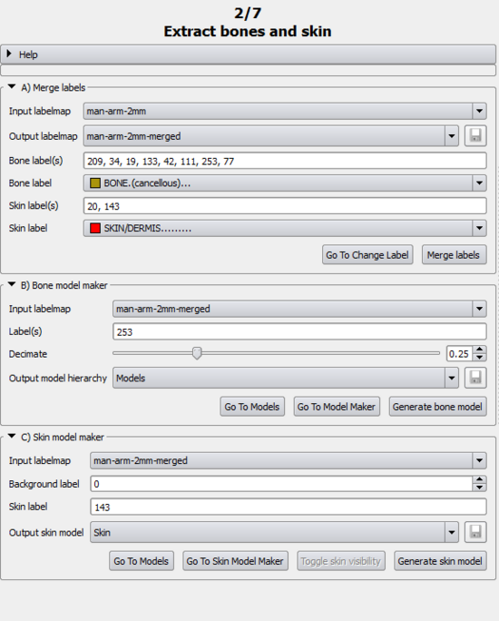
2) Extract bone and skin
The 2) Extract bone and skin page deals with creating the bone and skin model that will serve as references and watch dogs for the posing.
A) Bone model maker
This helps to create the bone model.
Simple workflow
- Output model hierarchy: Select the output model hierarchy under which the bone model will be stored.
- Generate bone model: Using the Model Maker, generate the bone model. The bone model will be used when placing the armature. It allows to place the armature bones on top the real bones for a better and more natural posing.
Advanced workflow
- Label(s): Select the label that will be used to create the bone model. By default, it automatically uses the label from Bone Label (in 1) A)).
- Go To Models: Opens the Models module.
- Go To Model Maker: Opens the Models Maker module. The Models Maker allows to generate the model corresponding to any (or all) the label of a given labelmap using marching cubes. The module can give more control over the smoothing, normal computation...
B) Skin model maker
This section is in charge of creating the skin model.
Simple workflow
- Output: Select the output model for the skin model.
- Toggle skin visibility: Toggle the visibility of the model selected in Output.
- Generate skin model: Using the Grayscale Model Maker, extract the outer surface of the Input Labelmap. The skin model can be used to help find the right pose with no overlaps by using the 5) Pose Armature(posing).
Advanced workflow
- Input Labelmap: Select the labelmap that will be used to create the skin model.
- Threshold: Select the threshold that will be used to differentiate the body in the labelmap from the outside (usually air). Default is 0.1.
- Go To Models: Opens the Models module.
- Go To Grayscale Model Maker: Opens the Grayscale Model Maker module. The module give more control computation parameters such as the smoothing, the computation of the normal, etc...
|
 Extract bone and skin panel |
3) Create armature (rigging)
Note: When opening this page, the view will automatically switch to 3D Only to help creating/visualizing the armature.
A) Armatures
The armature (either created or loaded) is the interface between the user and the transformations needed to pose the volume models. Once completed, the armature rest positions should not be changed since it would necessitate all the following computation to be updated as well. It is therefore highly encouraged to save the created armature in order to be able to restore it with Load armature from model.
Simple workflow
- Toggle Skin visibility: Does the same as Toggle Skin Visibility in 2) B). It is advised to turn off the skin visibility so when placing bone, they automatically will drop at the same depth as the skeleton model instead of the skin model.
- Load armature from model: Prompts a dialog window to open an armature from a model. See Armatures module for further details.
- Go To Armature Module: Opens the Armatures module.Armatures module allows the user to modify the armature by adding, tweaking, deleting bones in Rest mode. The display properties of the armature like X-Ray mode, opacity, color or shape can also be modified there.
|
|
4) Compute weights (skinning)
The Compute weights section is where each voxel of the input image gets attributed a weight that represents by how much it is influence by a given bone movement.
Note: When opening this page, the view will automatically switch to Four Up.
A) Volume skinning
To compute a weight, the skinning volume must first be computed. The skinning represents what bones influences the most a given voxel.
Simple workflow
- Volume: Select the volume/labelmap that will be used for the skinning.
- Armature: Select the armature associated with the Volume.
- Output skinned volume: Select the output volume.
- Skin volume: Compute the skinned volume. The output skinned volume is a labelmap where each voxel of the input Volume is associated with a bone of the input Armature. This means that if we were to use binary weights, a given voxel will move exactly as its associated bone in the skinned volume. For this reason and as the skinned volume drives the weight computation, it can be very profitable to tweak this results, most notably in joints area.
Advanced workflow
B) Compute armature weight
The weight computation is then refined further in order to consider the influence of every bone on a given voxel.
Simple workflow
- Output weight image folder: Select the folder where the weight images will be saved.
- Compute weights: Compute the weight image. For each bone of the Armature a weight image is created. A weight image stores by how much a given voxel of the Volume will be influenced when the associated bone moves. This computation is based on the solving of a heat-diffusion equation for which the bones of the volume represent the hot source. To increase computation speed, the input images are first downsampled by a scale factor. The resulting weight image is then upsampled back to the original image spacing.
Advanced workflow
- Volume: Select the volume/labelmap that will be used for the weight computation. It should be the that was used for the A) Volume Skinning.
- Armature: Select the armature associated with the Volume. It should be the that was used for the A) Volume Skinning.
- Input skinned volume: Select the skinned volume. It should be the (possibly tweaked) volume associated with the Volume and the Armature.
- Go To Compute Armature Weights Module: Opens the Compute Armature Weight module. In the Compute Armature Weight module, the user can further refine the computation of the weight by, for example, restricting it to a given bone or the downsampling factor.
|
|
5) Pose armature (posing)
This page is meant to help the user to find the right pose before starting the 6) Pose labelmap by posing a model interactively.
Note: When opening this page, the current armature (if any) will automatically switch to Pose mode.
A) Evaluate surface weight
The first step is to evaluate the weight at each vertices of the model using A) Evaluate surface weight.
Simple workflow
- Output surface: Select the output surface with the weight evaluated for each of its points.
- Evaluate surface weight: For each point of the Input Surface, evaluates of the influence of all weight and add it as a field array. This will improve the computational time of the Pose Surface.
Advanced workflow
- Input surface: Select the input surface that will have the weight evaluated on.
- Weight images folder: Select the folder where the weight images are.
- Go To Evaluate Surface Weight Module: Opens the Evaluate Weight module.
B) Armatures
This just serves as a quick link to the Armature module, should it be needed.
Simple workflow
- Go Armature Module: Opens the Armatures module. In that case, the Armatures module can be used to reset the current pose to its originals rest value. This can be useful in order to create a clean pose.
C) Pose surface
This poses any surface according to the armature. Usualy, the skin and bone models give a fairly good idea of what the result of the 6) Pose labelmap will look like.
Simple workflow
- Output surface: Select the output surface that will store the posed Input Surface.
- Pose surface: This will pose the Input Surface according to the posed Armature and the weight images from the given Weight images folder. If the surface was evaluated, this will automatically use the evaluated weight to compute the posed surface. If not it will read the weight from the Weight images folder to do so (slower computation). If the checkbox is activated, the CLI will automatically run anytime any of the input is modified. Otherwise, the CLI will only run once. This steps operates as a prelude to 6) Pose Labelmap. When posing the skin and/or the skeleton, the user can assert the quality of the weights as well as fine tune the pose interactively. Once the pose is satisfying, it can then be applied to the labelmap.
Advanced workflow
- Armature: Select the posed input armature.
- Input surface: Select the input surface that will be posed.
- Weight images folder: Select the folder where the weight images are.
- Go To Pose Surface Module: Opens the Pose Surface module.
|
|
6) Pose labelmap
Final step of the workflow, the 6) Pose labelmap uses the posed armature and the weights associated with it to compute the posed labelmap.
A) Resample labelmap with pose
Pose a labelmap given an armature and the weights associated with it.
Simple workflow
- Output posed labeldmap: Select the output labelmap that will store the posed Input labelmap.
- Apply: This will pose the Input labelmap according to the posed Armature and the weight images from the given Weight images folder. As this steps may take quite some time, it is highly encouraged to first try to pose the skeleton to make sure that the pose does not create any anatomical error. The skin model should also be posed to verify that there is no overlap (to make sure for example that the hand does not enter the thigh).
Advanced workflow
- Armature: Select the posed input armature.
- Input surface: Select the input labelmap that will be posed.
- Weight images folder: Select the folder where the weight images are.
- Go To Pose Labelmap Module: Opens the Pose Labelmap module. It can be useful to tweak some of the parameters like the Maximum radius to prevent the computation to take too much time.
|
|
Similar Modules
Developer Information