ParaView/Users Guide/VTK Data Model
Introduction
To use ParaView effectively, you need to understand the ParaView data model. Here, we will introduce the the VTK data model used by ParaView briefly. For more details, you can refer to one of the VTK books.
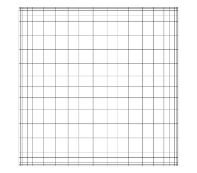
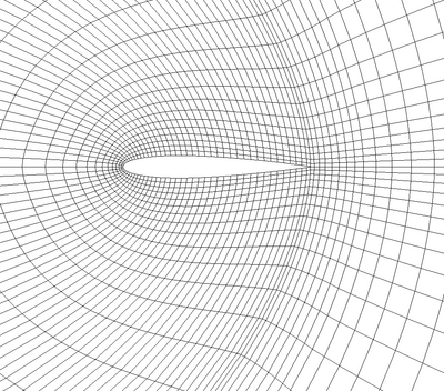
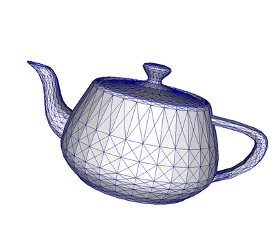
The most fundamental data structure in VTK is a data object. Data objects can either be scientific datasets such rectilinear grids or finite elements meshes (see below) or more abstract data structures such as graphs or trees. Since ParaView is geared toward scientific visualization, we will focus on the former and touch briefly on the latter when necessary.
Datasets are formed of smaller building blocks: mesh (topology and geometry) and attributes.
Mesh
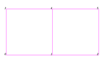
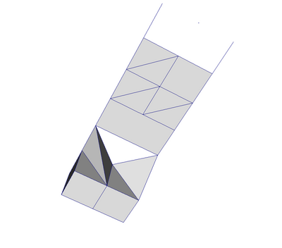
Even though the actual data structure used to store the mesh in memory depends on the type of the dataset, some abstractions are common to all types. We describe these here and we briefly describe the data structures below for each dataset. In general, a mesh consists of vertices (points) and cells (elements, zones). Cells are used to discretize a region and can have various types such a tetrahedra, hexahedra etc. Each cell contains a set of vertices. The mapping from cells to vertices is called the connectivity. Note that even though it is possible to define data elements such as faces and edges, VTK does not represent these explicitly. Rather, they are implied by a cell's type and its connectivity. One exception to this rule is the arbitrary polyhedron which explicitly stores its faces. Here is an example mesh that consists of 2 cells. The first cell is defined by vertices (0, 1, 3, 4) and the second cell is defined by vertices (1, 2, 4, 5). These cells are neighbors because they share the edge defined by the points (1, 4).
So far, we talked about the topology only. A mesh is fully defined by its topology and the spatial coordinates of its vertices. In VTK, the point coordinates may be implicit or explicitly defined by a data array of dimensions (number_of_points, 3).
Attributes (fields, arrays)
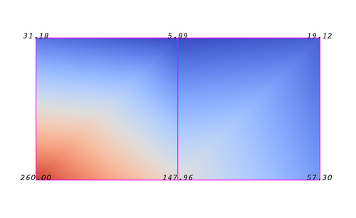
An attribute (aka data array or field) defines the discrete values of a field over the mesh. Examples of attributes include Pressure, Temperature, Velocity and Stress Tensor. Note that VTK does not specifically define different types of attributes. All attributes are stored as data arrays which can have an arbitrary number of components. ParaView makes some assumptions in regards to the number of components. For example, a 3 component array is assumed to be an array of vectors. Attributes can be associated with points or cells. It is also possible to have attributes that are not associated with either. The following example demonstrates the use of a point-centered attribute. Note that the attribute is only defined on the vertices. Interpolation is used to obtain the values everywhere else. The interpolation functions used depends on the cell type. See VTK documentation for details.
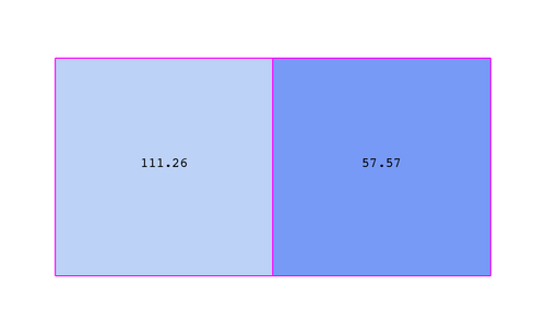
The figure below demonstrates the use of a cell-centered attribute. Note that cell-centered attributes are assumed to be constant over each cell. Due to this property, many filters in VTK cannot be directly applied to cell-centered attributes. It is normally required to apply a Cell Data to Point Data filter. In ParaView, this filter is applied automatically when necessary.
