Beginning GUI: Difference between revisions
No edit summary |
No edit summary |
||
| Line 125: | Line 125: | ||
*Also, note that you can move where the camera is pointing by changing the Focal Point. | *Also, note that you can move where the camera is pointing by changing the Focal Point. | ||
[[Image:beginning_gui_10.png]] | [[Image:beginning_gui_10.png|800px]] | ||
Revision as of 01:41, 12 January 2010
Introduction
This usecase presents a few of the more important new ParaView 3.X GUI features. A full list of features can be found in the online help.
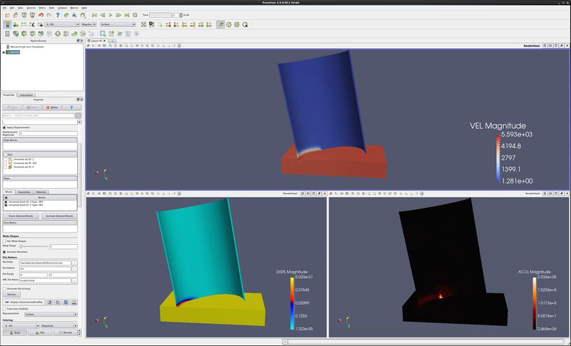
The paraview viewscreen can now be split. This allows a user to see multiple aspects of their data at one time, or to display in multiple data files side by side.
Data is opened by going to File → Open. Example data files can be found on the ParaView web page at http://www.paraview.org
Split windows
- Open can.exo. Press Apply.
- Drag the can around with the left mouse button until you can see the can.
- Split screen vertical – i.e., one above the other. This is the little box with the horizontal line.
- Select 3D View.
- Turn the eyeball on for can, in the Pipeline Browser.
- Split screen vertical – i.e., one above the other. This is the little box with the horizontal line.
- Select 3D View.
- Turn the eyeball on for can, in the Pipeline Browser.
- This last was a mistake. Undo, Undo, Undo. Undo is the red counter clockwise button.
- Select the bottom viewport.
- Split screen horizontal – i.e., one next to the other. This is the little box with the vertical line.
- Select 3D View.
- Turn the eyeball on for can, in the Pipeline Browser.
- Now lets link the cameras. Right click on the upper window, and click on Link Camera. Click on the lower right window. Do the same between the two bottom windows.
- Click in the lower left window, color by DISPL. Turn on Color Legend Visibility.
- Click in the lower right window, color by ACCL. Turn on Color Legend Visibility.
- Click in the upper window, color by VEL. Turn on Color Legend Visibility.
- Go to the last frame, click on Rescale to Data Range, go to first frame, play.
Move/control windows
- Select the top window. Apply a clip filter to this window. Filters/ Common/ Clip/ Apply. Deselect the Show Plane check box.
- Click on the Maximize button of the upper window.
- Click the Restore button of the upper window.
- Next, using the left mouse button, grab the title bar of the lower left window and drag/drop it into the upper window. These two windows have now switched places.
- Finally, grab the divider between the two lower windows and drag it left and right. You can also move the divider between the upper and lower windows.
Unlink windows
- To unlink the windows, we use the Link Manager. Tools/ Manage Links. Select the second link, and click Remove. Close.
- Now, grab and rotate can in the three windows.
- Finally, delete the bottom two windows, using the Close button.
Control the center
- Click on the Show Center icon. Notice that this toggles the center cross.
- Click on the Pick Center icon, then select a location on the can. Rotate the can, and notice where it is rotating.
- Click on the Reset Center icon, returning the rotation location and center cross to the center of the object.
- You can always recenter the object using the Reset icon.
Move the camera
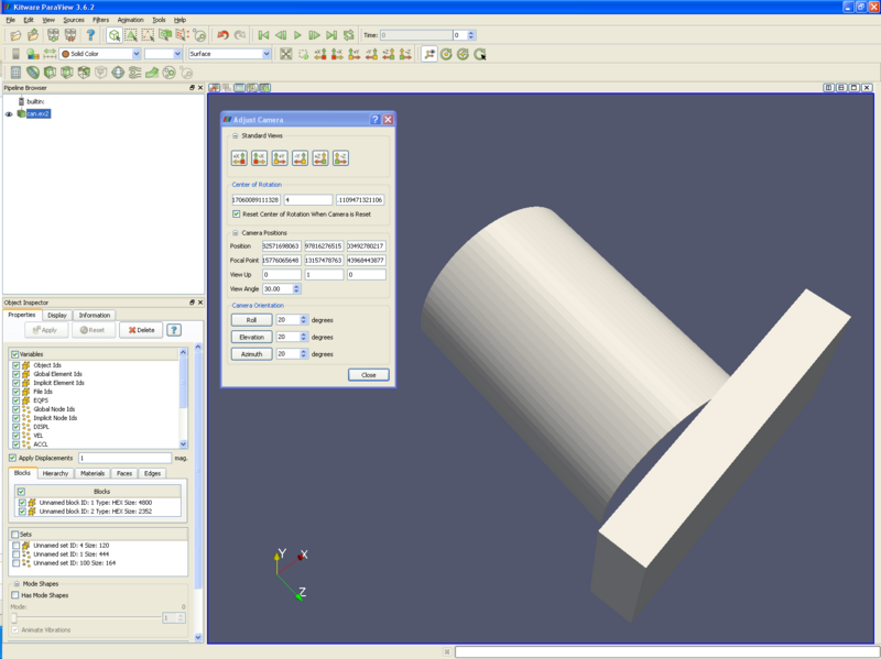
ParaView allows the user to change the position of the camera. Such controls as Roll, Elevation and Azimuth are available. The Adjust Camera icon is on the right side of the row of icons at the top left of the 3d window. It looks like this:
The Adjust Camera dialog box looks like this:
Useful controls that I often use (in order) are as follows:
- Azimuth - rotate around the vertical axis. Be sure to hit the button after entering a number.
- Elevation - rotate around the horizontal axis in the plane of the screen.
- Roll - rotate around the axis coming out of the screen.
- View angle - basically a zoom in.
- Camera position - where the camera is.
- Focal point - where the camera is looking.
- View Up - I don't know what this is.
- You can always recenter the object using the Reset icon. First, however, be sure to change View angle back to 30.
Color Map
- Select the DISPL variable.
- Move forward one time step using the Next Frame icon.
- Click on the Rescale to Data Range icon.
- Click on the Toggle Color Legend Visibility icon.
- Click on the Edit Color Map icon.
- The Color Scale Editor is used to change the colormap. The online help covers the Color Scalar Editor (Help → Help → ParaView → Object Inspector → Display Panel → Color Selection).
- Select the Use Logarithmic Scale icon. Notice what has happened to the colors on the can. Unselect Use Logarithmic Scale icon.
- Select the Choose Preset icon. Choose Cool to Warm, then OK. Notice what has happened to the colormap. This is an easier to understand colormap than the rainbow one that all of us are use to. Next, choose the Blue to Red Rainbow preset. Although harder to understand (requiring an understanding of the layout of the rainbow colors), this one makes prettier pictures.
- Uncheck the Automatically Rescale to Fit Data Range checkbox. Select Rescale Range.
- We can now select the variable ranges for the color range. Since I know the range of the data for DISPL, input 0 for the minimum and 20 for the maximum. Hit the Rescale button.
- I found these numbers by going to time step 0, doing a Rescale to Data Range and using this number for the minimum, and repeating the process for the last time step to find the maximum.
Adjust Camera
- Open can.exo. Press Apply.
- Click on the -Z icon, placing the can in the default orientation.
- There are a number of icons just above the 3d window, on the left side. Select the right most icon, the Adjust Camera icon.
- The Adjust Camera dialog is used to move the camera in precise steps. For instance, if you want to rotate the can base down by 45 degrees, type 45 in Elevation, and hit the Elevation button.
- Roll moves a number of degrees around the Z axis.
- Elevation rolls a number of degrees around the X axis.
- Azimuth rolls a number of degrees around the Y axis.
- Also, note that you can move where the camera is pointing by changing the Focal Point.
Menus and Help
- Open help. Help/ Help/ Contents/ + ParaView
- File menu. + File menu. Go over these entries.
- Edit menu. + Edit Menu. Go over these entries.
- View menu. + View Menu. Go over these entries.
- Sources menu. Show cone. Mention use of Cone and Sphere.
- Filters Menu. Show clip.
- Tools menu. + Tools Menu
Acknowledgements
Sandia is a multiprogram laboratory operated by Sandia Corporation, a Lockheed Martin Company, for the United States Department of Energy’s National Nuclear Security Administration under contract DE-AC04-94AL85000.

